Main Activities of The Laboratory:
- Designing of cooling systems for nozzle and rotor blades, rotors and stays of gas turbines.
- Experimental researches of hydraulics and thermal state of turbine elements including cooled blades on test bed and full-scale conditions.
- Designing, production and testing of gas turbine plant air boilers Inspection of gas turbine plant during scheduled preventive maintenance, examination of reasons for damageability of elements in gas turbine plants.
- Research on test bed and in full-scale conditions, designing and production of elements for exhaust paths of gas turbine plant.
- Development of gas flow stabilization methods.
- Designing, production and research of elements of gas turbine plant air inlet path including volutes.
- Performance of various research and development on combined cycle gas turbines including development of technical proposals on CCGT of various types, development of thermal circuits for CCGT, selection of main and auxiliary thermal and mechanical equipment for CCGT and steam-turbine plant.
- Designing and production of nonstandard equipment including heat exchange devices and silencers.
- Research and designing of antiicing systems for gas turbine plants.
- Determination of environmental characteristics (noise levels and heat emission) of thermal and mechanical equipment for gas turbine plant and CCGT.
- Designing, production and installation of noise and heat insulation of thermal and mechanical equipment of full-scale gas turbine plants and CCGT.
- Gas turbine blade row research bed
Experimental bed is designed for the research of hydraulic features and thermal condition of blade rows of gas turbines.
Main element of the bed is the high-temperature gas dynamics unit, which underwent modernization in 2013 – 2016.
Main parameters of the unit:
- maximum gas temperature – 1100°C,
- maximum gas temperature – 2,5 bar,
- cooling air temperature – 20 до 350°C.
The unit consists of combustion chamber, which receives the compressed air from K-500 compressor (motor power – 3500 kW, flow – G = 10 kg/s, Р = 6 bar), gas conditioning zone, work area, replaceable sets of researched and auxiliary blades.
The gas conditioning zone is designed for equalizing the gas temperature and pressure fields before the gas enters the work area.
It consists of several elements:
- a mixer, which mixes the flow after it leaves the combustion;
- chamber and the water-cooled elbow (angled at 90°);
- turbulizer (which consists of several perpendicular rods);
- honeycomb-type dashpot, which is made if perpendicular panels that form;
- a honeycomb-like structure with the cell size 40 x 40 mm;
- a convergent tube.
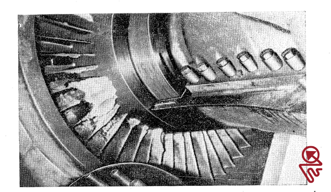
The work area consists of a water-cooled outer shell and an inner shell with installed sets of prepared experimental and auxiliary blades.
The new liquid-fuel combustion chamber features a refractory liner with combined convection and film cooling and dual-fuel single-stage nozzle with atomizing function. The new combustion chamber features the gas pilot burner (fed from the tank).
The following systems are also featured in the bed:
- the fuel system that feeds the diesel fuel to the combustion chamber burners,
- water system that feeds the water to the cooled outer shells of the unit and nozzles that inject water to the combustion projects behind the work area,
- the system that conditions and feeds the cooling are to the blades, as well as electric heaters.
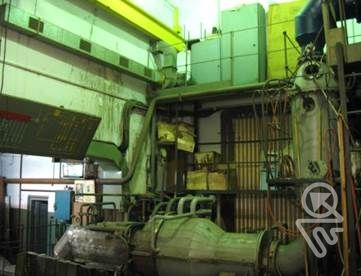
General view of the test bed after modernization
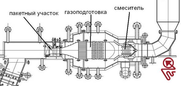
Layout of the unit
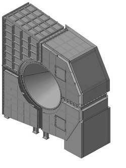
- Exhaust Line Research Test Rig
The department has created a special experimental unit. It was used in research of the exhaust line of PGU-325 unit, which includes GTE-110 gas turbine unit.
The exhaust line of the unit (hereafter EL) consists of the gas turbine diffuser (TD), exhaust manifold (EM) of GTE-110, which is considered a diffuser from the aerodynamic point of view, diffuser of the heat recovery boiler (DHRB), heat recovery boiler (HRB), HRB adaptor.
The experiments performed with the unit enabled the following:
- determine the main reason of occurrence of pressure pulsations in the EL gas flow;
- issue recommendations for lowering the pressure pulsations and check them during the experiment;
- determine hydraulic losses in diffusers.
Based on performance of K-500 axial compressor, in order to obtain the required Mach number value in the flow and match the field conditions, the department used the value 11.11 as the condition simulation factor. The layout of the unit is displayed below.
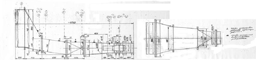
Unit layout
В состав экспериментальной установки входили:
- ресивер, входной стыковочный участок, участок закрутки для 3-х разных режимов работы натурного агрегата: холостого хода, 50 % нагрузки, номинального режима;
- модели диффузора турбины, модель выхлопного патрубка, модель переходного участка, модель диффузора котла-утилизатора;
- модель КУ с первым трубным пучком и эквивалентной моделью собственно котла.
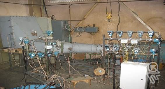
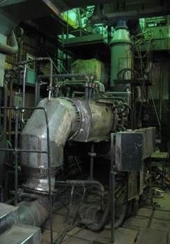
General view of the unit
Works Performed
Starting from 2012, the department has been performing a lot of works aimed to ensure reliable operation of the unique domestically-produced gas turbine unit GTE-110 by UEC Saturn. The following works have been performed to ensure the turbine operation:
- comprehensive analysis of the unit design, which determined main structural disadvantages of the unit;
- project and modernization of the unique high-temperature test bed designed for testing GTE-110 and GTE-110M blades;
- several series of experimental researches of nozzle guide vanes and blades of one stage of GTE-100 turbine at the gas temperature of 1100 °C;
- based on the design analysis and a set of assessments of blade damages, the department has developed and released blade optimization recommendations.
For the sake of experimental research, full-scale blades on the test bed were fitted with two types of thermocouple with XA labeling: for the main part of the blade – approximately 50 thermocouples in soft siliceous thread insulation saturated with silicone lacquer (thermocouple wire diameter – 0.3 mm); the trailing edge zone is fitted with thermocouple cables that have the outer diameter of 0.5–0.7 mm.
Hot junctions were getting flattened and welded by electric resistance welding to the external surface of the blade at the cable groove end zone. The cable in grooves and hot junctions were getting enclosed by ≈0.1 mm think foil, which was getting welded to the blade by electric resistance welding. The air and gas temperature was measured using XA thermocouples in soft insulation with wire diameter of 0.5 mm.
Based on the obtained experimental data on hydraulic and thermal condition of various versions of nozzle guide vanes of GTE-110, we have verified the corresponding design models in 2D and 3D. Using the verified models, we have conducted calculations of hydraulic, thermal, stress and vibrational condition of blades for field environment. The Fig. A displays a comparison of experimental data on the blade with calculations. The Fig. B features the results of thermal condition design for one version of GTE-110 blade in a field environment.
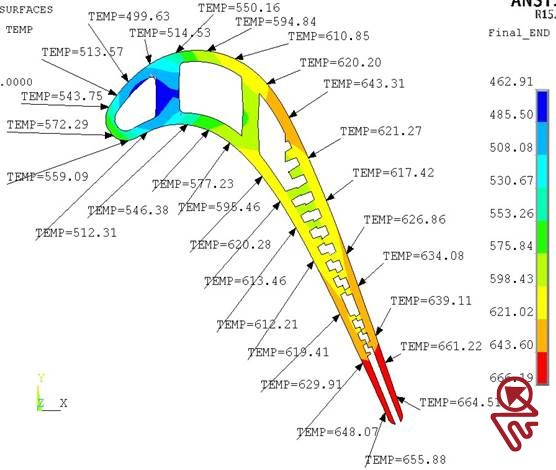
Fig. A. Verification analysis of the mid-section temperature field in the hot blowdown mode


Fig. B.
Based on the experiments and calculations performed, the department has developed specific suggestions regarding modernization of cooling systems and design of nozzle guide vanes and blades with the aim to extend their service life. The recommendations are included in the full-scale unit.
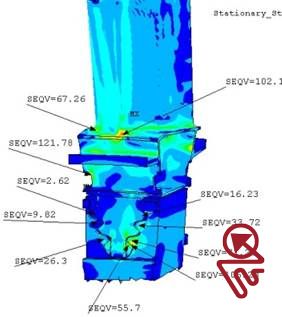

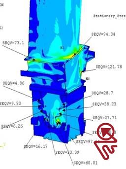
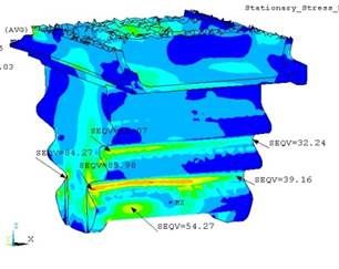

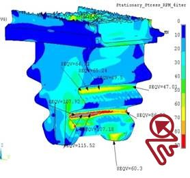


Heat stress condition calculation results in 3D projection of a blade at one stage of the turbine

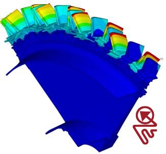
The results of vibration condition evaluation for the “disc-blades” system
of one stage of GTE-110 turbine
A set of studies aimed to determine the causes of flow pulsations in the exhaust line of GTE-110 unit by UEC Saturn, which lead to development of pulsation suppression method
The measurement scheme designed for the research includes several types of primary sensors and secondary equipment:
- Five-channel ball probe for measuring the speed value and direction in the flow. Secondary equipment – U-shaped differential pressure gauges with water and pressure gauges like Metran-100 DIV and Metran-100 DI;
- Pitot-static tube for measuring the flow parameters in the last measurement section and Metran-100 DIV;
- Pressure gauges like Metran-100 DIV for measuring static pressure during the extraction from the unit walls and to ensure operation of the pressure pulsation detection scheme;
- Ditran piezo pressure pulsation sensor and instrumentation complex by National Instruments.
Experimental research was conducted using the Re number in the self-similarity of flow. (Re > 1.5*105), and Mach numbers that match the full-scale values. For example, for the rated load mode at the axial flow to the turbine diffuser the tests were performed with the value М ≈0.47 (Re value was 3.76 * 105;). The pressure pulsation measurement has shown that the main reason of their occurrence is the flow whirling. (see Fig. E) The department has designed a pressure pulsation suppression method in the EL flow that is based on counter-whirling device. (see Fig. F)
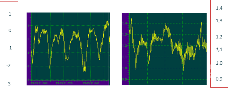
Pressure pulsation measurements

Flow pressure pulsation suppression in the EL
Works performed with 1.25–1.8 MW marine units produced by PSC «Proletarsky Zavod»
- The department has completed a design, production and testing of plate regenerator for the new marine unit GTG-1250 by PSC «Proletarsky Zavod».
- The department has received the industrial utility model patent. The patent is implemented in the commercial GTU.

Marine unit GTG-1250 R produced by PSC “Proletarsky Zavod”
Evaluation of environmental characteristics of PGU 325 equipment
- The noise levels have been measure in the turbine hall of PGU 325.
- The main noise sources have been determined.
- The recommendations have been issued with regard to reducing the noise emitted by the heat machinery equipment of the PGU.
- The department has designed modernization of sound insulation of the shelter, exhaust manifold, oil facilities, transmission and gas fuel system pipes. The Detail Construction Documentation has been released for the turbine shell heat insulation. New noise and heat insulation of the turbine shell was mounted on the full-scale unit.

3D модель новой шумоизоляции улитки агрегата ГТЭ-110.
Works on research of antiicing systems for gas turbine plant
- Complex of works on research of antiicing systems for gas turbine plants SGT-800, V 64.3А and ГТ-160 installed at power plants of TGC-1 PJSC in St. Petersburg is performed.
- Recommendations on optimization of algorithms for antiicing systems and their design.
- Economic losses from operation of antiicing systems and reduction of power in units within summer time.
- Proposals on implementation of “Tuman” system implementation.
- Complex of works on research on damaged inlet guide vane of compressors for 2 gas turbine plants SGT-100 installed in power center of Pulkovo Airport. Determination of reasons for blade damaging is icing in the area of inlet guide vanes.